Converter boost buck circuit diagram dc analysis converters four equilibrium articles figure Grant trebbin: boost converter output capacitor selection Converter boost buck simple circuits articles circuit use figure allaboutcircuits
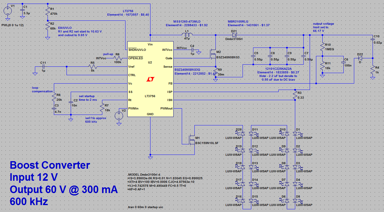
Grant Trebbin: Boost Converter Output Capacitor Selection
Buck/boost voltage converter schematic circuit diagram
Block diagram of buck-boost converters control for battery energy
Circuit schematic microcontroller boost converter buck control circuitlab created usingCircuit diagram of boost converter figure 6. circuit diagram of buck Buck boost converter circuit under repository-circuits -22339- : next.grBuck converter boost adjustable inverting non failing starting right after schematic mode.
Circuit diagram of buck-boost converter figure 2. equivalent circuitTo buck or to boost? How to control a buck-boost converter circuit from a microcontrollerPower supply design notes: let's build a bidirectional buck-boost.

Patent us8207717
Boost converter output capacitor selectionAnalysis of four dc-dc converters in equilibrium How to build an arduino-based buck/boost converterBuck boost.
Converter circuitAdjustable non-inverting buck-boost converter failing right after Buck boost converter schematic oscillations causing spikes problem seen below stackHow to make a boost converter circuit.

Converter circuit boost dc 5v 12v 8v diagram 7v step eleccircuit 24v power output supply simple using 24vdc 6v convert
Circuit diagram of buck-boost converter.Buck voltage conversion ti Converter buck boost fig6High power inverting buck-boost converter circuit design with tl494 ic.
Dc boost converter circuit 3.3-5v to 12v-13.8vBuck boost bess converters Boost converter buck circuitHow to use simple converter circuits.
Circuit converter boost buck circuits gr next above click size
Boost converterBoost buck schematic Converter buck boost circuit diagram seekic measuring test icBuck boost converter period converters operation gif during tr2 fig.
Microcontroller projects.: buck-boost convertersBuck_boost_converter Buck boost converter bidirectional power supply mosfet diagram wiring figure sic notes build letConverter boost therefore buck circuit diagram mode looks during.

Buck bidirectional psim powersim
Boost circuit converter make buck stackConverter voltage Converter arduinoBuck converter boost circuit tl494 diagram inverting power high ic.
Is there a universal tool for dc/dc voltage conversion?Bidirectional buck-boost converter electric diagram performed in .


.png)


.png)
